Ortrun Bargholz The Attempt to Achieve Coherence: Contradictions in the historical plan material relating to Schinkel’s Bauakademie in Berlin
1.0 Introduction
There are plans to re-erect the Bauakademie (Academy for Architecture) in Berlin’s ‘historic center.’ The brief for the competition for The Reconstruction of the Bauakademie Berlin as the National Academy of Building1 suggests “design approaches under the motto ‘as much Schinkel as possible.’”2 The competition documents state that the historical volume should be adhered to, and that “reference to the historical design in terms of form and material is expressly called for.”3
But what is the basis for the assumption that it is possible to reconstruct the Bauakademie true to its original state? What does “historical design in terms of form and material” involve? And what does the competition’s motto, ‘as much Schinkel as possible,’ actually mean? In the following, I outline the fundamental complexity—or even impossibility—of attempts towards an accurate reconstruction through the identification and discussion of contradictions in surviving plan materials. In addition to the analysis of the content of the sources, the necessary constructs and working methods are to be described rigorously as a formal process in all its detail but also fatigue.
When a building’s plans are handed down to us, the information about the building in question seems certain. This is the case with Karl Friedrich Schinkel’s Bauakademie, which was erected between 1832 and 1836 under the supervision of the public building construction official Emil Flaminius. In 1836, in the first four issues of the Wiener Allgemeine Bauzeitung, Flaminius wrote On the construction of the building for the generalist school of building in Berlin.4 The plans by Flaminius, published in conjunction with this text, are the only ones that can illustrate the building as built at that time. All other surviving plans either date from earlier design phases or represent later proposals for adaptations. Even though the last drawings produced by Schinkel himself date from 1831,5 it can be assumed that the changes depicted in Flaminius’ plans from 1836 were made in close collaboration with Schinkel and even though the communication during the construction process has not been documented, we can take it that these further developments were approved by Schinkel.6
Sources
If we include in the planning and construction period of the Bauakademie (1831-1836) the publications that appeared later (up to 1838), there are 52 drawings in existence.7 It is primarily these drawings that will be examined here.
However, as a basis for comparison, later drawings found in the course of intensive archive research work are also included, in particular the scaled plans produced by the Meisterwerkstatt III (masters’ workshop) under the direction of Richard Paulick (1952-1956),8 the survey drawings from the 1950s,9 the survey notes by Herbert Reichert (1961),10 as well as the detailed elevation drawing of the corner of the Bauakademie reconstructed by Martina Abri and Christian Raabe in Berlin (2001).11 Their research is largely based on an evaluation of the remnants of the original molding stones.12
It is easy to overlook the wide diversity of plans produced during the design process and the numerous differences between such plans and the building ultimately erected—and not only in the case of the Bauakademie. In regards the Bauakademie, the plans described above, as well as later supplementary auxiliary information, have been handed down to us at many points and it is difficult to establish a coherent relationship between the different items of existing material—even through the most precise analysis of the plans, texts, and photographs.13
This essay is based on the aim to produce a joint reference system for the divergent plans. On this basis, the contradictions between them are analyzed, and the gaps in available information are shown. In addition, a survey is taken of what happened in the course of the attempt to achieve coherence: under what circumstances, with which means and limitations was the work carried out, and what are the results that can be expected given the contradictory nature of the sources?
For the purpose of my inquiry, Schinkel’s ideas and intentions are of interest above all else, but in their most highly developed form, i.e., the state that was ultimately realized. I see the built form—if we disregard unintentional inaccuracies in the construction—representing Schinkel’s ideal state, given the assumed close collaboration between Schinkel and Flaminius. Consequently, it should be emphasized that what is examined here is an approach to detailed fictive planning and non-existent survey plans following completion in an idealized form. Conversely, this also means that the observations below do not correspond to all the details of the Bauakademie in the form it was built.
With this text I aim to work through what it means, at a certain distance in time, to ‘reconstruct’ this form (the fictive state of planning at the end of a partially documented planning process). The excessive attention to detail, the complexity and the contradictions of this text reflect an important aspect of this reconstruction work. It is in this way that I wish to show the demanding analytical processes and speculative decisions that lie behind the supposedly simple demand for “reference to the historic design in terms of form and material”—at least if such a call is understood as meaning more than just an approximately similar appearance.
2.0 Legibility of the Plans
2.1 Requirements
: Appendix I, and Emil Flaminius, “Der Durchschnitt nach a-b der Grundrisse von der allgemeinen Bauschule in Berlin,” in Allgemeine Bauzeitung vol. 1, no. 2 (1836): appendix IV.")
Figure 1.0. Two scale bars from the Flaminius plans, overlaid by the author. Original scale bars from 1. Emil Flaminius, “Die Fassade der allgemeinen Bauschule in Berlin,” Allgemeine Bauzeitung 1, no. 1 (1836): Appendix I, and Emil Flaminius, “Der Durchschnitt nach a-b der Grundrisse von der allgemeinen Bauschule in Berlin,” in Allgemeine Bauzeitung vol. 1, no. 2 (1836): appendix IV.
In order to reconstruct something, we must reactivate information from a form of representation, such as a plan. The plan promises that it preserves and stores precise and technical details about a building; it was drawn with the intention that it would be read later. Like the original building process, today’s plans can be read and decoded, in a kind of re-enactment.
Unfortunately, not a single construction plan of the Bauakademie was archived,14 and only the first design plans and illustrations that appeared in publications have survived. In neither case were these plans intended to serve as a basis for construction. Therefore, it is uncertain whether what is drawn matches what was built. The illustrations could, conceivably, show an older version, or they might have been idealized for representation purposes.
Independent of this fact, to allow a plan to be decoded, the two-dimensional representation must meet four fundamental requirements:
- The plan must be drawn to scale (or contain enough information so that it could be reproduced to scale).
- In all dimensions, the plan must follow this same scale, i.e., it must be free of distortions.
- The scale used must be known. This scale must be given either in the form of a drawn scale bar or as a proportional scale figure, and it must agree with the drawing.15
- The plan must be legible, i.e., the conventions of the coding and the plan graphics must be known.
All of the available plans of the Bauakademie meet these four requirements only in part—at least, in the formats in which they were available to me as working material. For instance, since the digitization of the plan collection, the plans in the Berlin based Kupferstichkabinett16 are usually available to users only in digital form.
Therefore, it is unclear whether the distortions are in the drawing itself, in the physical material of the plan, whether they are due to the reprographic process, or to the processing of the images by the archive.
2.2 Scales
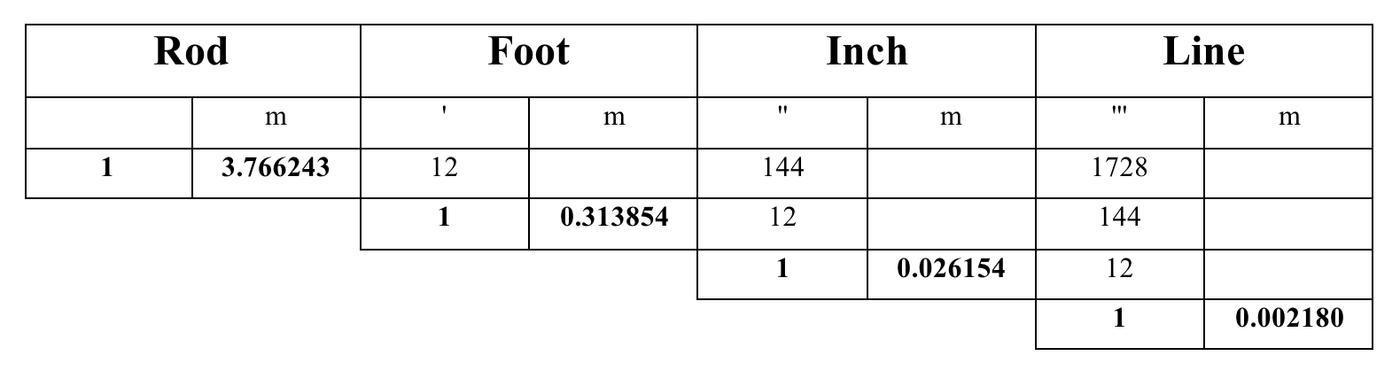
In using the plan material dating from the 1830s, we are confronted with the difficulty of converting it to the metric system of measurement.17 Most of the plans have a scale bar in feet, which, however, do not correspond with the Imperial foot still commonly used today. At the time the building was erected, the measurement of length used in Berlin was the Prussian foot. Until the beginning of the nineteenth century a number of different regional foot scales were used, however, in 1816, a uniform system was introduced. It seemed logical, therefore, to assume that the plans of the Bauakademie are based on a foot measuring 31.3853543 cm.
The foot system of measurement
In 1771, the Royal Building Commission moved to propose the Rhineland foot (with 139.13 Paris lines) as the standard foot because it was already widely used.18 This standardization was implemented by a Direktorialbefehl (executive order) on October 28, 1773, and consequently the renamed rheinländischer Werkfuß (Rhineland foot) measuring 139.13 Paris lines was officially introduced in all Prussian states except Silesia.
However, the term ‘Rhineland foot’ is misleading. The foot actually used in the Rhineland was defined as 139.1835 Paris lines.19 Therefore, the term Brandenburg foot is preferable, which Eytelwein suggested as early as 1798 in order to avoid confusion.20 Around the same time in Paris (from 1791) various original forms of the meter based on the Paris foot (pied de roi) were introduced, 21 but were only recognized by the German Reich much later, in 1875.
In the Maaß und Gewicht-Ordnung from May 16, 1816, the ‘Prussian foot’ was decided upon as the basic unit of measurement. Although the name was officially changed from Rhineland to Prussian foot, the length remained the same at 139.13 Paris lines.22
The foot system of measurement
If we take this contemporary definition of the foot as a basis and scale all of the plans using the scale bars depicted on them to arrive at a uniform scale, we do not find any consistency between them. The information that can be read from the plans is contradictory, and, according to both the foot scale bar and the meter scale bar given, the Bauakademie would be a different size in almost every plan.
: Appendix I; Emil Flaminius, “Die Grundrisse des Kellergeschosses und Erdgeschosses der allgemeinen Bauschule in Berlin,” Allgemeine Bauzeitung 1, no. 1 (1836): Appendix II; Emil Flaminius, “Die Grundrisse der obern Stockwerke,” Allgemeine Bauzeitung 1, no. 2 (1836): Appendix III; Emil Flaminius, “Der Durchschnitt nach a-b der Grundrisse von der allgemeinen Bauschule in Berlin,” Allgemeine Bauzeitung 1, no. 2 (1836): Appendix IV.")
Figure 2.0 A comparison of scale bars in the Flaminius plans. The scale bars in the Flaminius plans from the Allgemeine Bauzeitung contain, in part, both a foot and a meter scale. However, it is only in section that these scales agree with the assumed conversion figure, where 1 foot equals 31.3854 cm. If one scales all the plans according to the foot scale bar, then there are significant deviations of up to 7.32% to the meter scale bar. Even within the Flaminius set of plans, these differences are entirely inconsistent and remain an inexplicable contradiction. Montage by author. Sources used include Emil Flaminius, “Die Fassade der allgemeinen Bauschule in Berlin,” Allgemeine Bauzeitung 1, no. 1 (1836): Appendix I; Emil Flaminius, “Die Grundrisse des Kellergeschosses und Erdgeschosses der allgemeinen Bauschule in Berlin,” Allgemeine Bauzeitung 1, no. 1 (1836): Appendix II; Emil Flaminius, “Die Grundrisse der obern Stockwerke,” Allgemeine Bauzeitung 1, no. 2 (1836): Appendix III; Emil Flaminius, “Der Durchschnitt nach a-b der Grundrisse von der allgemeinen Bauschule in Berlin,” Allgemeine Bauzeitung 1, no. 2 (1836): Appendix IV.
If one overlays two drawings of a similar kind and orientation they should, essentially, be congruent and should not contradict each other—at least if they come from the same set of drawings. But in the case of the Flaminius plans from 1836, even this purely content-related comparison, independent of any scale, does not bring us any further. Although they are of the same width and aligned with the same elements, the section and the elevation differ in height.23 Clearly, the depictions must be wrong or else wrongly reproduced.
3.0 Construction of a System of Reference
It is prudent to create an axial reference system in order to render plans legible and to be able to compare them, despite any formal contradictions. Creating a reference system facilitates finding the causes of the contradictions—independent of the scale problem. In addition, the incompatibility between the plans and the chosen grid as a system of reference allows for discrepancies in the latter to be recognized. Below, an explanation of how the axial reference system is produced and can be used as an absolute reference.
3.1 Façade Axes
To provide a basis for a system that is independent of the scales, a constant must be used that remains unchanged in the course of the planning process: in the case of the Bauakademie, this is the system of axes in the façade. All four façades consist of eight elements of the same format, separated from each other by projecting pilasters. These can be found in the first of Schinkel’s design drawings from 1831—and they are clearly scaled.24
The axial (center-to-center) dimension is the sum of the width of one pilaster and the width of the space between two pilasters. The width of the pilasters, which widen towards the plinth, is 42” (1.098487 m) in the upper area, and the width of the space between the pilasters is 170” (4.446259 m). The center-to center (axial) dimension is therefore 212” (5.544746 m). Each of the windows is placed centrally in its façade element so that the windows are the same distance apart from each other, but this dimension is shifted by half an axial bay (the distance from the center of a window to the center of a pilaster). This axial dimension of 212”, or the relationship between the pilasters and the recessed areas between them, is borrowed as a hypothesis from Schinkel’s plans.
This dimension was first validated by a survey made in the 1950s,25 albeit with tolerances. Raabe later checked this dimension using the survey photographs of the building taken in 1911 together with the dimensions of the original bricks.26 It is assumed that the brick dimensions and the width of the joints of standard bricks are known.27 However, some sources do not agree with this assumption.28 The discrepancies here are slight, but they add up. And these discrepancies are relevant when calculating the building’s overall height, for they fail to provide the precise brick and joint dimensions that could otherwise be used for reconstruction planning.
Variances in the external dimensions
In the 1950s two surveys were made of the Bauakademie’s external dimensions: one by the Ingenieur- und Vermessungsbüro Schenk (engineering and surveying office Schenk) in 1953, the other by Kollektiv Schenk (Schenk Collective) in 1957. Although there were only four years between these surveys—and they were made on-site by the same person—the results are not uniform. The two surveys contradict each other, and they do not provide a basis upon which any reliable statements can be made. While the discrepancies are not serious, they cannot be ignored. Banal at first, they become increasingly significant when considered in the context of contemporary planning in which “from-to” dimensions cannot be used. In reconstruction, the demonstrable variations in the Bauakademie as built (even though it is unclear how extensive they were) would have to be eliminated, as clear decisions are needed to erect a building. Incidentally, Martina Abri and Christian Raabe laid out the model reconstruction of the corner using an external dimension of 46.345 m for the plinth.
Even though the relative differences between the two external dimensions for each façade amount to only between 3 cm and 4 cm, the absolute maximum difference is 10 cm (46.33 m vs. 46.43 m). Given the widespread assumption that all four elevations are the same, this difference is not insignificant.
| Measured at the plinth = basement | Measurement by Ingenieur- und Vermessungsbüro Schenk (Paul Schenk), October 195329 | Measurement by Kollektiv Schenk, 30. and 31.1.195730 | Difference |
|---|---|---|---|
| North (Entrance) | 46.39 m | 46.43 m | +4 cm |
| West | 46.33 m | 46.36 m | +3 cm |
| South | 46.36 m | 46.36 m | 0 cm |
| East (Spree) | 46.35 m | 46.38 m | +3 cm |
Corner pilasters
The corner pilasters are wider than the pilasters that lie between them: according to Schinkel by 5”,31 according to Raabe by one header, i.e., 4 ¾” brick width.32 In his elevation drawing, however, Raabe contradicts himself and draws a joint plus a header, which is 4 ¾” + ½ ”= 5 ¼”. Raabe’s drawing seems plausible, as, in brick walls, two bricks must be separated by a joint. Photogrammetric images confirm this joint work. Therefore, in my reflections, I assume a corner pilaster dimension of 42”+ 5 ¼” = 47¼” (1.235798 m). The slight difference to the dimension of 1.24 m from Herbert Reichert’s survey in 1961 can be accepted due to imprecise measurement.33 According to Schinkel’s dimensioning the pilasters project 10” from the wall plane.34 This would represent exactly the length of a brick—but without the joint. On the other hand, Raabe writes that in all of Schinkel’s plans, the clear internal dimension matches the distance between the projecting pilasters, which would give a projection of 10¼” (47¼” corner pier dimension – 37” wall).35 According to a survey from the 1950s, the wall plane is set back by 26 cm36 (9.94”) and, therefore, tends to confirm Schinkel. These inaccuracies are not surprising within the usual tolerances of masonry construction, but nevertheless, they leave small contradictions. Since I was unable to arrive at a final clarification, I oriented myself on the inner edges of the corner pilasters in scaling the plans.
While the sources are quite consistent regarding the axial distance (even though it is frequently rounded off to 5.55 m), giving an exact dimension for the corners is more complicated.
According to Raabe’s drawing, the widening of the piers towards the pedestal and again towards the plinth amounts on each side to a joint and the width of a brick, i.e., 5¼” (0.137311 m). However, the problems already mentioned also exist here.
On the upper floors, this produces a total external dimension of 1748” (45.731077 m vs. E.K.S. 1952: 45.76 m), which, due the widening of the pilasters towards the base, increases to a calculated external dimension of 1769½” (46.280320 m). Below the sandstone band, a slightly further widening is discernible; however, these dimensions cannot be precisely determined. The surveyed values here lie between 46.33 m and 46.43 m (see above).
. The elevation drawing by Christian Raabe is used for the comparison (on the right, in blue). The legend for the axial system is light blue for the center axes of the pilasters, dark blue for the outside edges of the pilasters, red for the widening of the corner pilasters, and yellow for the center axes of the windows. Montage by author. Sources used include Karl Friedrich Schinkel's Bauakademie Berlin. Aufriss von drei Jochen der Hauptfassade, 1831, SMB-KK SM 31.14; Gustav Stier, Bauakademie Berlin. Aufriss von vier Jochen der Hauptfassade, 1831, SMB-KK SM 31.25; Emil Flaminius, “Die Fassade der allgemeinen Bauschule in Berlin,” Allgemeine Bauzeitung 1, no. 1 (1836): Appendix I; Alfred Meydenbauer, Berlin, Alte Bauakademie, Messbild axial von Westen, 1911, BLDAM 3m12/129.5; Richard Paulick and Deutsche Bauakademie Meisterwerkstatt III, “Schinkel-Akademie Berlin, Ansicht,” scale 1:50, 1953, SMB-ZA II A-BV, BA 59; Abri+Raabe Architekten, “Ansicht Musterecke (Ostseite),” scale 1:50, Eine Ecke der Bauakademie. Zur Rekonstruktion der Allgemeinen Bauschule Karl Friedrich Schinkels, (Berlin, 2011), insert.")
Figure 3.0 Depiction of the axial system. A comparison is made between selected historical elevations and a photograph in order to determine the extent to which they agree with the axial system. In each case, a strip of the drawings available is depicted in full width (not all drawings show the complete façade). The elevation drawing by Christian Raabe is used for the comparison (on the right, in blue). The legend for the axial system is light blue for the center axes of the pilasters, dark blue for the outside edges of the pilasters, red for the widening of the corner pilasters, and yellow for the center axes of the windows. Montage by author. Sources used include Karl Friedrich Schinkel’s Bauakademie Berlin. Aufriss von drei Jochen der Hauptfassade, 1831, SMB-KK SM 31.14; Gustav Stier, Bauakademie Berlin. Aufriss von vier Jochen der Hauptfassade, 1831, SMB-KK SM 31.25; Emil Flaminius, “Die Fassade der allgemeinen Bauschule in Berlin,” Allgemeine Bauzeitung 1, no. 1 (1836): Appendix I; Alfred Meydenbauer, Berlin, Alte Bauakademie, Messbild axial von Westen, 1911, BLDAM 3m12/129.5; Richard Paulick and Deutsche Bauakademie Meisterwerkstatt III, “Schinkel-Akademie Berlin, Ansicht,” scale 1:50, 1953, SMB-ZA II A-BV, BA 59; Abri+Raabe Architekten, “Ansicht Musterecke (Ostseite),” scale 1:50, Eine Ecke der Bauakademie. Zur Rekonstruktion der Allgemeinen Bauschule Karl Friedrich Schinkels, (Berlin, 2011), insert.
According to Raabe, the comparison with survey photographs confirms the dimensions for the façade axes given by Schinkel, and apart from slight discrepancies of less than 1 cm, axial dimensions agree with the original figures of 1831. This suggests the hypothesis that these basic dimensions were retained without changes during the design phase. I, therefore, use this axial dimension as the basis for a reference system, a theoretical, somewhat hypothetical construction in which the other plans, whatever their given scale, can be inserted. Thus, with the help of the axial system for analysis, all that is needed is an inherently consistent scale whereby, through the use of reference points, plans can be adapted to the axes.
3.2 Floor plan grid
The system of distances between axes, as described above, can be applied to all the façades. In the next step, the façade axes can be expanded to form a two-dimensional floor plan grid; they cross through the building and connect the opposite façades with each other. This grid is also shown in the floor plans. All the internal walls and columns lie within the widths of the pilasters (dark blue lines) even though in detail they are not placed centrally, and the impression should by no means be given that the floor plan rigidly follows the grid.

Figure 4.0 The expansion of the axial system to create a floor plan grid. Drawing by author.
In reality, the volume of the Bauakademie is not right-angled and identical in all directions, a fact that emerges in the Sketch for Examining the Building’s Rectangularity by Kollektiv Schenk from 1957.37 Still, one can assume that all of the plans of the Bauakademie depict a desired ideal state. Furthermore, given the elaborate nature of Schinkel’s system of measurement, it is highly unlikely that small irregularities were deliberate. It can be assumed that differences in angles and dimensions were not intentional, but arose during construction.38 In the context of seeking to approach Schinkel’s ideal state, these imprecisions can be disregarded for it is worth emphasizing that our object of study here is a reconstruction of the planning of the Bauakademie—not of the building as erected.
If we examine the Flaminius floor plans from 183639 in conjunction with the axial system, it quickly becomes clear that the drawings are not square. A more precise examination discovers objects such as the dome above the staircase or the columns in the rooms, which clearly were circular but in the plans are shown compressed, i.e., distorted. This leads to the assumption that as part of a contemporary true-to-scale reconstruction, the plans should be rectified and fitted into a square or into Schinkel’s axial system.
 and the dome above the main staircase (top right) should be circular. If we rectify the plans using the axial system as a basis, they are then shown correctly (bottom left and right). Montage by author. Sources used include Emil Flaminius, “Die Grundrisse der obern Stockwerke,” Allgemeine Bauzeitung 1, no. 2 (1836): Appendix III.")
Figure 5.0 Examining rectification using circles in the floor plans. Both the column (top left) and the dome above the main staircase (top right) should be circular. If we rectify the plans using the axial system as a basis, they are then shown correctly (bottom left and right). Montage by author. Sources used include Emil Flaminius, “Die Grundrisse der obern Stockwerke,” Allgemeine Bauzeitung 1, no. 2 (1836): Appendix III.
However, if we insert the idealized floor plans in the axial system, it becomes clear that the plans also contain inherently imprecise information. Even after the most scrupulous correction of all distortions, many elements that must be continuous from floor to floor, such as the hot air ducts and the columns, do not lie directly over each other.
: Appendix II, and “Die Grundrisse der obern Stockwerke,” Allgemeine Bauzeitung 1, no. 2 (1836): Appendix III.")
Figure 6.0 The floor plans of the ground floor and first floor from the Flaminius set of plans, overlaid. Montage by author. Sources used include Emil Flaminius, “Die Grundrisse des Kellergeschosses und Erdgeschosses der allgemeinen Bauschule in Berlin,” Allgemeine Bauzeitung 1, no. 1 (1836): Appendix II, and “Die Grundrisse der obern Stockwerke,” Allgemeine Bauzeitung 1, no. 2 (1836): Appendix III.
Given the rather small scale of the plans (as they were published in a journal, were primarily intended as illustrations), and considering the drawing equipment available at the time, such imprecision is easily explained. Nevertheless, it prevents us from making clear statements about Schinkel’s ideal form for the historical Bauakademie, as there is no other way in which the interior—as built—can be examined.40
3.3 Heights
The real problem in decoding the plans is presented by the missing third dimension, the height. As argued earlier, the scale and scale bars of the sections and elevations contradict each other; no consistent scale exists. In contrast to the horizontal plane, in the façades’ verticals, there are no identifiable constants that could be used to produce a system of reference based on the principles outlined above. Consequently, the photographs taken from 1886 onwards remain the only source of auxiliary information, but they are linked to a series of specific problems.
The problems presented by the survey photographs
Photographs are of limited use. Camera lenses introduce distortions, and the lens required to record the Bauakademie without distortions would need a diameter of at least 20 meters, which is practically impossible. We do not know the exact model of lens that the survey institute used for its photographs, which makes a digital correction of the lens impossible. It should also be mentioned that, given the perspective distortion in photographs, only objects in the same plane can be compared with each other in terms of scale.41
The apparent freedom from distortion suggested at first glance by the survey photographs of the Bauakademie—an impression created by the fact that the outlines of the building are almost parallel to the edges of the image—does not, in fact, exist.
The comparison is restricted to relative information as no scale was included in the photograph. Consequently, for instance, the (purely relative) examination of the relationship between the pilasters and the spaces between them, as described above, can be carried out without difficulty by means of the survey photographs.
The difference in the distance between the pilasters and the plane of the window wall, which lies somewhat deeper, itself produces serious distortions in the photographs. Depending on the aspect examined, the photograph must always be scaled according to the plane being looked at, i.e., according to the pilasters or the window axes.
In the case of the recessed roof parapet, a further difficulty is that in the photographs taken at eye level, a significant part of this parapet is hidden by the eaves cornice, a further example of the trickiness of the radial field of view of camera optics.
The established reference model works in the vertical to a limited degree. We cannot be certain that the vertical dimensions were not altered in the planning process. As an aid for comparing vertical dimensions, I have used a detailed elevation of the façade reconstruction by Christian Raabe.42 From this, to mark all important façade elements, I have drawn reference lines that allow the other plans to be compared. And as there are no fixed reference dimensions that could be used to correct them, the elevations and sections to be compared retain any distortions they may have in the vertical. Other distortions, however, were removed, so that the drawings are right-angled.
 and the rectified (adjusted, in black) version of Flaminius’ section drawing overlaid. Transformations caused by rectification have been kept to a minimum in order not to change the scale bars. Montage by author. Sources used include Emil Flaminius, “Der Durchschnitt nach a-b der Grundrisse von der allgemeinen Bauschule in Berlin,” Allgemeine Bauzeitung 1, no. 2 (1836): Appendix IV.")
Figure 7.0 Rectified section drawing. The distorted (original, in red) and the rectified (adjusted, in black) version of Flaminius’ section drawing overlaid. Transformations caused by rectification have been kept to a minimum in order not to change the scale bars. Montage by author. Sources used include Emil Flaminius, “Der Durchschnitt nach a-b der Grundrisse von der allgemeinen Bauschule in Berlin,” Allgemeine Bauzeitung 1, no. 2 (1836): Appendix IV.
, taken from Christian Raabe’s elevation in blue. Montage by author. Sources used include Abri+Raabe Architekten’s “Ansicht Musterecke (Ostseite),” scale 1:50, found on the back cover of Eine Ecke der Bauakademie (Berlin, 2011).")
Figure 8.0 The axial system is expanded by adding vertical construction reference lines (in green), taken from Christian Raabe’s elevation in blue. Montage by author. Sources used include Abri+Raabe Architekten, “Ansicht Musterecke (Ostseite),” scale 1:50, Eine Ecke der Bauakademie. Zur Rekonstruktion der Allgemeinen Bauschule Karl Friedrich Schinkels, (Berlin, 2011), insert.
Accordingly, the elevations and sections were scaled only in the horizontal in accordance with the axial reference system. An exception here is the section by Flaminius, whose height, as already mentioned, contradicts the elevation by Flaminius in the same publication. I assume that the height of the elevation applies to both drawings. This assumption can be justified with the help of the detailed staircase sections that appeared in the same publication: they match the overall section drawing exactly if the latter is compressed in height to 97.2% and adapted to match the elevation.
Fixed point in the vertical
The apparently obvious reference point of the surrounding terrain, if looked at more closely, reveals itself as unreliable, for the ground around the Bauakademie is very uneven—although it is unclear to what extent this is the case. Therefore, as the point of insertion of the plans in the reference system, I chose the continuous sandstone cornice that runs between the ground floor windows and the basement windows, marking the baseline of the Bauakademie visually. It extends the top step of the entrance steps around the entire building. Assuming that there is no change in level between the top step of the entrance flight of steps and the vestibule, the upper edge of this base cornice is at the same level as the ground floor in the entrance area.
Information about everything that lies below this sandstone molding is sparse. The only plan that depicts the junction of the plinth and the ground on all sides is by Stier and dates from 1831—but it does not show what was built between 1832 and 1836.43 All other sets of plans are restricted to the presentation of one façade, generally, the north front with the main entrance, in which the connection of the plinth to the ground is shown as level. Even the detailed records of the war damage made by the Zentrales Büro für Hochbau (Central Building Construction Design Office of the Ministry of Reconstruction) in the 1950s44 used only an exemplary elevation as a basis and ignored the differences in height in the plinth area.
The only dimension that shows levels for the junction of the plinth and the ground is in a site plan drawn by Ingenieur- und Vermessungsbüro Schenk in 1953.45 According to this plan, the maximum difference between the highest point (to the left of the entrance portal) and the lowest point (at the south-east corner of the building) is 48 cm. The incline along the south façade is given as only 11 cm. In earlier photos taken at the end of the nineteenth and beginning of the twentieth century the incline is clearly greater.46 However, on account of the way the photograph was taken, this cannot be measured precisely.
The comparison of the early photos with those taken after the war justifies the assumption that that the area around the building and the footpath were redesigned sometime between the end of the nineteenth century and the 1950s and, as a result, the connection of the plinth to the ground was changed. Consequently, the site plan with levels that dates from 1953 does not allow us to draw conclusions about the plinth-ground connection in 1836.
 by Alfred Meydenbauer (Berlin, Alte Bauakademie, Messbild Übereck-Ansicht von Südosten, 1911, BLDAM 3m14/129.7) and right photograph (cutout) by Helmut Maier (Bauakademie vor dem Wiederaufbau, von Südosten, 1959, private archive)")
Figure 9.0 A comparison of the incline at the base of the plinth along the south side of the Bauakademie. Left photograph (cutout) by Alfred Meydenbauer (Berlin, Alte Bauakademie, Messbild Übereck-Ansicht von Südosten, 1911, BLDAM 3m14/129.7) and right photograph (cutout) by Helmut Maier (Bauakademie vor dem Wiederaufbau, von Südosten, 1959, private archive)
Previously, I constructed a reference system that allows for the plans to be compared despite missing, erroneous, or inconsistent scales. Elevations and sections can be adapted in the horizontal, and in the vertical they can, at least, be oriented to a reference point. At this point it should be stated that the reference system established earlier can be used only to compare plans in which information about dimensions is missing or erroneous with each other and does not allow us to say anything about the actual or absolute states that would be required for a (reconstruction) building.
4.0 Applying the reference system
The attempt to apply this reference system practically quickly reveals the hypothetical nature of the construct. For instance, the question about the height of the roof parapet—and with it the total height of the building—soon shows that generally speaking, precise statements about the building can be made only with reservations and only if restricted to very specific areas. The roof parapet and other examples are explored below.
4.1 Example: building and story heights and roof parapet
: plate 117 (vol. 20, plate 123, 1833); Emil Flaminius, “Die Fassade der allgemeinen Bauschule in Berlin,” Allgemeine Bauzeitung, 1, no. 1 (1836): Appendix I; E.K.S. (Eggert, Knauf, Schreiber), “Ansicht Bestandszeichnung Aufmass Bauakademie,” scale 1:100, Güstrow 1952, IRS Wiss. Samml. C_11-59; Richard Paulick and Deutsche Bauakademie Meisterwerkstatt III, “Schinkel-Akademie Berlin, Fassaden-Detail,” scale 1:20, 1952, BArch DH 2-PLAN/2865, sh. 1; Richard Paulick and Deutsche Bauakademie Meisterwerkstatt III, “Schinkel-Akademie Berlin, Ansicht,” 1953: SMB-ZA II A-BV, BA 59; and Abri+Raabe Architekten, “Ansicht Musterecke (Ostseite),” scale 1:50, Eine Ecke der Bauakademie. Zur Rekonstruktion der Allgemeinen Bauschule Karl Friedrich Schinkels, (Berlin, 2011), insert.")
Figure 10.0 All elevations placed side by side. From each plan, a section measuring one axial bay was chosen. Green lines mark the sill heights, and the sandstone surrounds to the windows, as well as prominent cornices and decorative façade elements, after Raabe. The bays are arranged in chronological order. Montage by author. Sources used include Karl Friedrich Schinkel, Bauakademie Berlin. Aufriss von drei Jochen der Hauptfassade, 1831: SMB-KK SM 31.14; Gustav Stier, Bauakademie Berlin. Aufriss von vier Jochen der Hauptfassade, 1831: SMB-KK SM 31.25; Karl Friedrich Schinkel, “Bauakademie Berlin. Fassadenaufriss,” Sammlung architektonischer Entwürfe, (Berlin, 1858): plate 117 (vol. 20, plate 123, 1833); Emil Flaminius, “Die Fassade der allgemeinen Bauschule in Berlin,” Allgemeine Bauzeitung, 1, no. 1 (1836): Appendix I; E.K.S. (Eggert, Knauf, Schreiber), “Ansicht Bestandszeichnung Aufmass Bauakademie,” scale 1:100, Güstrow 1952, IRS Wiss. Samml. C_11-59; Richard Paulick and Deutsche Bauakademie Meisterwerkstatt III, “Schinkel-Akademie Berlin, Fassaden-Detail,” scale 1:20, 1952, BArch DH 2-PLAN/2865, sh. 1; Richard Paulick and Deutsche Bauakademie Meisterwerkstatt III, “Schinkel-Akademie Berlin, Ansicht,” 1953: SMB-ZA II A-BV, BA 59; and Abri+Raabe Architekten, “Ansicht Musterecke (Ostseite),” scale 1:50, Eine Ecke der Bauakademie. Zur Rekonstruktion der Allgemeinen Bauschule Karl Friedrich Schinkels, (Berlin, 2011), insert.
If we compare the heights of the depicted plans, the differences are evident at first glance. Although there is no reliable approach that can help us to discover whether the plans are distorted vertically (see Section 3.3), for each set of plans, the section and elevation can be compared in terms of the total height or individual story height, and we can look for agreements between the different sets of plans to find confirmation of certain information. One danger of this approach is, of course, that it could lead to the use of information that was already erroneous in the original.
; Karl Friedrich Schinkel: Bauakademie Berlin. Fassadenaufriss, Berlin 1858: AM-TUB SAE 1858,123; Karl Friedrich Schinkel, “Bauakademie Berlin. Fenster- und Gürtungsgesimse, Fensterprofil,” Sammlung architektonischer Entwürfe, Berlin 1858, plate119 (= vol. 20, plate 125, 1833); Emil Flaminius, “Der Durchschnitt nach a-b der Grundrisse von der allgemeinen Bauschule in Berlin,” Allgemeine Bauzeitung 1, no. 2 (1836): Appendix IV; Emil Flaminius, “Die Fassade der allgemeinen Bauschule in Berlin,” Allgemeine Bauzeitung 1, no. 1 (1836): Appendix I; Emil Flaminius, “[Portal- und Fassaden-]Details zur allgemeinen Bauschule in Berlin,” Allgemeine Bauzeitung 1, no. 4 (1836): Appendix VII; Richard Lucae, Projekt zum Umbau der Bau-Akademie, Schnitt a-b, 1875, AM-TUB 10723; Alfred Meydenbauer, Berlin, Alte Bauakademie, Messbild axial von Westen, 1911: BLDAM 3m12/129.5; Unknown, Ehemaliges Bauakademie-Gebäude Grundriss des III. Stockwerkes [und Schnitt mit Geschosshöhen], scale 1:100, approx.1913, SMB-ZA I-BV, BA 07; E.K.S. (Eggert, Knauf, Schreiber), Entwurf Bauakademie Schnitt, scale 1:100, Güstrow 03.1952, IRS Wiss. Samml. C_11-59; E.K.S. (Eggert, Knauf, Schreiber),Ansicht Bestandszeichnung Aufmass Bauakademie, Güstrow 1952: IRS Wiss. Samml. C_11-59; Richard Paulick and Deutsche Bauakademie Meisterwerkstatt III, Schinkel-Akademie Berlin, Schnitt A-B, scale 1:50, 22.08.1953, SMB-ZA II A-BV, BA 10; Richard Paulick and Deutsche Bauakademie Meisterwerkstatt III, Schinkel-Akademie Berlin, Schnitt C-D, scale 1:50, 22.08.1953, SMB-ZA II A-BV, BA 58; Richard Paulick and Deutsche Bauakademie Meisterwerkstatt III, Schinkel-Akademie Berlin, Fassaden-Detail, 1952, BArch DH 2-PLAN/2865, sh. 1; Richard Paulick and Deutsche Bauakademie Meisterwerkstatt III, Schinkel-Akademie Berlin, Ansicht, 1953, SMB-ZA II A-BV, BA 59; Richard Paulick and Deutsche Bauakademie Meisterwerkstatt III, Schinkelakademie Berlin, Hauptgesims, scale 1:5, 1956, BArch DH 2-PLAN/298; Unknown, Bauakademie Berlin. Skizze Attika [bemaßt], without year, BArch DH 2-PLAN/2865, sh. 17; Herbert Reichert, Bauakademie Berlin. Aufmaß-Skizzen, 20.06.1961, IRS Wiss. Samml. C_16-4; Helmut Maier, Bauakademie Westseite, 1959, Private archive; Abri+Raabe Architekten: “Ansicht Musterecke (Ostseite),” scale 1:50, Eine Ecke der Bauakademie, (Berlin, 2011), insert; Abri+Raabe Architekten, “Musterfassade, Zeichnung Kranzgesimsgeländer. Plan-Rekonstruktion nach Fotoauswertung, zur Ausführung vorgesehen,” Mythos Bauakademie: die Schinkelsche Bauakademie und ihre Bedeutung für die Mitte Berlins, Exhibition catalogue, (Berlin, 1998), 56.")
Figure 11.0 Comparison of the different sets of plans in relation to the building height. Montage by author. Sources used include Karl Friedrich Schinkel, Bauakademie Berlin. Querschnitt durch einen Flügel, 1831, SMB-KK SM 31.13; Karl Friedrich Schinkel, Bauakademie Berlin. Aufriss von drei Jochen der Hauptfassade, 1831: SMB-KK SM 31.14; Gustav Stier, Bauakademie Berlin. Halber Querschnitt, 1831, SMB-KK SM 31.24; Gustav Stier, Bauakademie Berlin. Aufriss von vier Jochen der Hauptfassade, 1831: SMB-KK SM 31.25; Karl Friedrich Schinkel, “Bauakademie Berlin. Lageplan, zwei Grundrisse und Querschnitt,” Sammlung architektonischer Entwürfe, Berlin 1858, plate 116 (= vol. 20, plate 122, 1833); Karl Friedrich Schinkel: Bauakademie Berlin. Fassadenaufriss, Berlin 1858: AM-TUB SAE 1858,123; Karl Friedrich Schinkel, “Bauakademie Berlin. Fenster- und Gürtungsgesimse, Fensterprofil,” Sammlung architektonischer Entwürfe, Berlin 1858, plate119 (= vol. 20, plate 125, 1833); Emil Flaminius, “Der Durchschnitt nach a-b der Grundrisse von der allgemeinen Bauschule in Berlin,” Allgemeine Bauzeitung 1, no. 2 (1836): Appendix IV; Emil Flaminius, “Die Fassade der allgemeinen Bauschule in Berlin,” Allgemeine Bauzeitung 1, no. 1 (1836): Appendix I; Emil Flaminius, “[Portal- und Fassaden-]Details zur allgemeinen Bauschule in Berlin,” Allgemeine Bauzeitung 1, no. 4 (1836): Appendix VII; Richard Lucae, Projekt zum Umbau der Bau-Akademie, Schnitt a-b, 1875, AM-TUB 10723; Alfred Meydenbauer, Berlin, Alte Bauakademie, Messbild axial von Westen, 1911: BLDAM 3m12/129.5; Unknown, Ehemaliges Bauakademie-Gebäude Grundriss des III. Stockwerkes [und Schnitt mit Geschosshöhen], scale 1:100, approx.1913, SMB-ZA I-BV, BA 07; E.K.S. (Eggert, Knauf, Schreiber), Entwurf Bauakademie Schnitt, scale 1:100, Güstrow 03.1952, IRS Wiss. Samml. C_11-59; E.K.S. (Eggert, Knauf, Schreiber),Ansicht Bestandszeichnung Aufmass Bauakademie, Güstrow 1952: IRS Wiss. Samml. C_11-59; Richard Paulick and Deutsche Bauakademie Meisterwerkstatt III, Schinkel-Akademie Berlin, Schnitt A-B, scale 1:50, 22.08.1953, SMB-ZA II A-BV, BA 10; Richard Paulick and Deutsche Bauakademie Meisterwerkstatt III, Schinkel-Akademie Berlin, Schnitt C-D, scale 1:50, 22.08.1953, SMB-ZA II A-BV, BA 58; Richard Paulick and Deutsche Bauakademie Meisterwerkstatt III, Schinkel-Akademie Berlin, Fassaden-Detail, 1952, BArch DH 2-PLAN/2865, sh. 1; Richard Paulick and Deutsche Bauakademie Meisterwerkstatt III, Schinkel-Akademie Berlin, Ansicht, 1953, SMB-ZA II A-BV, BA 59; Richard Paulick and Deutsche Bauakademie Meisterwerkstatt III, Schinkelakademie Berlin, Hauptgesims, scale 1:5, 1956, BArch DH 2-PLAN/298; Unknown, Bauakademie Berlin. Skizze Attika [bemaßt], without year, BArch DH 2-PLAN/2865, sh. 17; Herbert Reichert, Bauakademie Berlin. Aufmaß-Skizzen, 20.06.1961, IRS Wiss. Samml. C_16-4; Helmut Maier, Bauakademie Westseite, 1959, Private archive; Abri+Raabe Architekten: “Ansicht Musterecke (Ostseite),” scale 1:50, Eine Ecke der Bauakademie, (Berlin, 2011), insert; Abri+Raabe Architekten, “Musterfassade, Zeichnung Kranzgesimsgeländer. Plan-Rekonstruktion nach Fotoauswertung, zur Ausführung vorgesehen,” Mythos Bauakademie: die Schinkelsche Bauakademie und ihre Bedeutung für die Mitte Berlins, Exhibition catalogue, (Berlin, 1998), 56.
 from Flaminius, 1836, is overlaid with a façade drawing (left, in blue) by Raabe, 2000, as well as a survey sketch (right, in blue, author and date unknown) and a detailed section of the roof parapet by Paulick from 1953 (also on the right, in blue). Montage by author. Sources include Emil Flaminius, “[Portal- und Fassaden-] Details zur allgemeinen Bauschule in Berlin,” in Allgemeine Bauzeitung 1, no. 4 (1836): Appendix VII, Fig. 3 and. Fig. 4; Unknown, “Bauakademie Berlin. Skizze Attika [bemaßt],” without year, BArch DH 2-PLAN/2865, sh. 17; Richard Paulick and Deutsche Bauakademie Meisterwerkstatt III, “Schinkelakademie Berlin, Hauptgesims,” scale 1:5, 1956, BArch DH 2-PLAN/298; Abri+Raabe Architekten, “Ansicht Musterecke (Ostseite)”, scale 1:50, Eine Ecke der Bauakademie, (Berlin, 2011), insert.")
Figure 12.0 Roof parapet details overlaid. Roof parapet details (elevation and section in black) from Flaminius, 1836, is overlaid with a façade drawing (left, in blue) by Raabe, 2000, as well as a survey sketch (right, in blue, author and date unknown) and a detailed section of the roof parapet by Paulick from 1953 (also on the right, in blue). Montage by author. Sources include Emil Flaminius, “[Portal- und Fassaden-] Details zur allgemeinen Bauschule in Berlin,” in Allgemeine Bauzeitung 1, no. 4 (1836): Appendix VII, Fig. 3 and. Fig. 4; Unknown, “Bauakademie Berlin. Skizze Attika [bemaßt],” without year, BArch DH 2-PLAN/2865, sh. 17; Richard Paulick and Deutsche Bauakademie Meisterwerkstatt III, “Schinkelakademie Berlin, Hauptgesims,” scale 1:5, 1956, BArch DH 2-PLAN/298; Abri+Raabe Architekten, “Ansicht Musterecke (Ostseite)”, scale 1:50, Eine Ecke der Bauakademie, (Berlin, 2011), insert.
If we look at the upper end of the building, we find agreement between the plans by Flaminius,47 Paulick,48 a survey sketch,49 and Raabe50 as regards the position of the crown cornice. However, the details are contradictory regarding the upper termination of the pilasters and the precise nature of the railings. With Flaminius and Paulick, the top elements are lower, with Raabe, they are taller. According to the survey of damage carried out by the Zentrales Entwürfsbüro für Hochbau in the 1950s51 all the top elements to the pilasters were destroyed. Still, according to Raabe, it was possible to find some of these elements among the debris and remnants of the building. Counting the layers of stone in the measured images in tandem with the sizes of stone and grout as a basic module while considering the remains of the molding stones enabled the determination and reconstruction of the exact condition of the cornice. It is significant that—providing this investigation correctly reflects the built condition—they do not conform to any of the plans.52
: Appendix IV; E.K.S. (Eggert, Knauf, Schreiber), “Entwurf Bauakademie Schnitt,” scale 1:100, Güstrow 1952, IRS Wiss. Samml. C_11-59; Richard Paulick and Deutsche Bauakademie Meisterwerkstatt III, “Schinkel-Akademie Berlin, Fassaden-Detail,” 1952: BArch DH 2-PLAN/2865, sh. 1; Richard Paulick and Deutsche Bauakademie Meisterwerkstatt III, “Schinkel-Akademie Berlin, Schnitt C-D,” scale 1:50, 1953, SMB-ZA II A-BV, BA 58; Abri+Raabe Architekten: „Ansicht Musterecke (Ostseite)“, scale 1:50, Eine Ecke der Bauakademie, (Berlin, 2011), insert.")
Figure 13.0 Comparison of height dimensions using section drawings from all plan sets—alongside the elevation by Raabe—with dimensions of room heights and ceiling or floor thicknesses as well as overall heights, in chronological order. Montage by author. Sources used include Karl Friedrich Schinkel, Bauakademie Berlin. Querschnitt durch einen Flügel, 1831, SMB-KK SM 31.13; Gustav Stier, Bauakademie Berlin. Halber Querschnitt, 1831, SMB-KK SM 31.24; Emil Flaminius, “Der Durchschnitt nach a-b der Grundrisse von der allgemeinen Bauschule in Berlin,” Allgemeine Bauzeitung 1, no. 2 (1836): Appendix IV; E.K.S. (Eggert, Knauf, Schreiber), “Entwurf Bauakademie Schnitt,” scale 1:100, Güstrow 1952, IRS Wiss. Samml. C_11-59; Richard Paulick and Deutsche Bauakademie Meisterwerkstatt III, “Schinkel-Akademie Berlin, Fassaden-Detail,” 1952: BArch DH 2-PLAN/2865, sh. 1; Richard Paulick and Deutsche Bauakademie Meisterwerkstatt III, “Schinkel-Akademie Berlin, Schnitt C-D,” scale 1:50, 1953, SMB-ZA II A-BV, BA 58; Abri+Raabe Architekten: „Ansicht Musterecke (Ostseite)“, scale 1:50, Eine Ecke der Bauakademie, (Berlin, 2011), insert.
In a comparison of the sections and the floor slabs’ thicknesses, the Flaminius section stands out clearly. Whereas in the earlier sets of plans, the floor slab between the ground and first floor is shown as around 47 cm thick, Flaminius drew a floor with a thickness of 95 cm. Although no information about the planning process is available, there must have been (unknown) reasons for such a dramatic change in the construction. It is surprising that in the later sets of plans, this floor thickness is drawn as only 38 cm. The only possible explanation for this is that the section lines cut through the barrel vault at different places. However, in Flaminius’s floor plan, the section line is clearly drawn along the center axis and, therefore, at the highest point of the vaulted ceiling, where the ceiling is thinnest.
4.2 Example: windows
If we compare the Flaminius elevation from 1836 with the survey photographs from the early twentieth century, it becomes clear that the windows were replaced sometime in the intervening period. This reveals a further aspect of the unreliability of the photographs as they always depict one specific state.
But for my observations, the construction from 1836 is of particular interest, as here Flaminius used a special kind of sliding window53—at least on some floors—to avoid outward opening window casements. This also helped to protect the terracotta elements.
The plans provide the only information that can be used for an analysis of the windows. The difficulties experienced in the evaluation of these are typical of the existing plans of the Bauakademie: while numerous drawings of the windows exist, none of these enables a complete or even consistent picture of the actual windows. The temporal and spatial gaps in the material dominate over congruent depictions.
Schinkel’s surviving original drawings from 1831 do not include any window details. In Stier’s papers from 1831, there are two window detail sheets;54 these are signed by Schinkel and show a construction with opening casements. In the collection of architectural designs by Schinkel from 1833, an elevation and section of a window on the first floor with opening casements were published,55 but it is only the details from Flaminius1836 that offer information about the sliding elements described.
The details in Flaminius’ plans refer to just one window on the second floor, as well as an elevation and a vertical section. They also show details, both vertical and horizontal, of the frame. Whether his detailed drawings are also applicable to the first-floor windows remains questionable. In his article Flaminius writes: “I therefore permit myself in this regard to depict only the construction that was chosen for the windows on the third floor […].”56
There is no information about the windows on the ground floor and the attic floor. Regarding the ground floor, there is only a description, along with detailed plans for the shops’ closure, but not of the windows.57 The question about the construction and frames of the windows in the courtyard remains unanswered.
Therefore, if the building is viewed as a whole, uncertainty about the exact design and actual construction of the windows is predominant. This is all the more surprising given the large number of detail drawings and illustrations.
4.3 Example: The floor levels on the ground floor
If we compare all of the surviving sections,58 it is noticeable that the Flaminius section from 1836 differs substantially from all the others: on the ground floor, different floor levels are shown. These are offset in relation to each other, and both levels differ from the assumed entrance level. If we insert Flaminius’ detailed staircase sections (which also show the vestibule floor), this confirms the assumption that the circumferential base cornice represents the level of the vestibule floor externally.59
This would mean that there were at least three different floor levels on the ground floor. However, the transitions between these levels cannot be read in the plans and remain completely unclear. We can assume that the floor level of the shops that occupied part of the ground floor of the Bauakademie was lower than that of the entrance area and the adjoining residential and storage spaces. A photograph from 1886, taken before the exterior ground floor redesign, reveals that the shops’ steps do not continue up to the sandstone band.60 In the Flaminius section, the shops are 0.475 m lower than the vestibule. A similar figure is found in the Eggert, Knauf, Schreiber section from 1952, in which an area that lies 0.46 m lower was depicted.61
 by Hermann Rückwardt, Die Bauakademie am Schinkelplatz bei der Schleusenbrücke, 1886, BPK Bild-Nr. 40004951.")
Figure 14.0 Stores on the east side of the Bauakademie facing the Spree. Photograph (cutout) by Hermann Rückwardt, Die Bauakademie am Schinkelplatz bei der Schleusenbrücke, 1886, BPK Bild-Nr. 40004951.
, the ground floor (top right), first floor (bottom left) and second floor (bottom right). Montage by author. Sources used include Emil Flaminius, “Die Grundrisse des Kellergeschosses und Erdgeschosses der allgemeinen Bauschule in Berlin,” Allgemeine Bauzeitung 1, no. 1 (1836): Appendix II, and “Die Grundrisse der obern Stockwerke,” Allgemeine Bauzeitung 1, no. 2 (1836): Appendix III.")
Figure 15.0 An annotation of the floor plans of the Bauakademie. The basement (top left), the ground floor (top right), first floor (bottom left) and second floor (bottom right). Montage by author. Sources used include Emil Flaminius, “Die Grundrisse des Kellergeschosses und Erdgeschosses der allgemeinen Bauschule in Berlin,” Allgemeine Bauzeitung 1, no. 1 (1836): Appendix II, and “Die Grundrisse der obern Stockwerke,” Allgemeine Bauzeitung 1, no. 2 (1836): Appendix III.
Efforts, using the plan, to discover the location of possible changes in the floor level fail due to the limitations of the available plan drawings, which are incomplete and, in terms of present-day conventions, erroneous.
See annotations in the floor plans of Figure 15.0:
- Basement towards the west: in the section, a basement is not shown under the depot, whereas in the basement plan it is.
- No differentiation is made between a door and an opening.
- The directions in which the doors open are not indicated and are therefore unknown.
- In shop unit 17, the stairs leading from the basement are missing; they are shown in the plan of the basement level but not the ground floor plan.
- The symbols used are not consistent: on all floors, the windows to the courtyard are drawn with three lines, whereas six openings on the ground floor are indicated by four lines. The meaning of this is unclear.
- All section lines in the staircases are missing. As a result, the areas underneath the staircases are not depicted.
4.4 Example: circulation routes and functions
As the information provided by the plans is inadequate, it is extremely difficult to make reliable statements about the circulation and about how and where the different functional units were separated from each other. If one moves around the Bauakademie building starting from the entrance, the following questions arise, the answers to which can only be a matter of speculation.
See annotations in the floor plans of Figure 15.0:
Ground Floor and Basement
- How were the apartments to the left and right of the vestibule entered? In each case, two openings are shown. One is directly on the first axis. On the second axis, the other opening is drawn in the plan as if it led directly to the stairs, which appears to be impossible. It is most probably meant as an opening below the stairs.
- At ground floor level was it possible to enter the courtyard from the vestibule? Probably not, as the courtyard lay considerably lower and the other doors from the courtyard led directly to the basement. However, it seems one had to cross the vestibule between the two main staircases to reach the rooms behind. This would also have been necessary to reach the ground floor rooms in which the casts and models were kept. Assuming that direct access from the courtyard was not possible—on account of the difference of level—they could only have been reached via this corridor behind the staircases.
- How did one reach the basement, apart from using the stairs in the shops? Could it be reached from under the main stairs (which were not drawn), or could one reach it only via the passageway to the side staircase that led to the basement, or from the courtyard through the doors leading directly into the basement?
- How did shop units 5, 9, 10, and 13 access their basement storage areas? Unlike the other shops, they had no direct connecting staircase.
- The tenants of shops 5 and 9 must have had to cross the courtyard to reach the southern door to the lobby, leading to their basement areas.
- Basements 10 and 13 reached their rooms via the same route, i.e., through the north-eastern basement door, but this would have entailed crossing a space that was marked as the storage space for shop 13. This only makes limited sense, as the basement stairs from shop 13 led to another neighboring room (which in all the other shops was the storeroom, but in the case of shop 13, was possibly too small). Alternatively, they would have had to walk through the northern courtyard door, along the façade and through one of the boiler rooms to reach their areas, which seems to have been a very circuitous route.
- On the ground floor a further question remains unanswered: what was the function of the room on the façade to the left of the passageway?
First floor
- Could the library be reached only through the teachers’ room? This seems unlikely, however in the right-hand teachers’ room—unlike in the left-hand one—there is no smaller opening indicated between the second and the third axis. Therefore, we can assume it was a continuous space.
Second floor
- Where did the apartment of the Schinkel family begin? Descriptions tell us that the north-eastern corner room was Schinkel’s study, that the neighboring room contained the plaster cast collection, and that the small room between the study and staircase was a hall. It remains unclear where the publicly accessible staircase hall was separated from the private rooms of the apartment. The corridor bordering the courtyard on the third axis was unusually spacious, and it was also not subdivided.
- How were the living rooms used? The subdivision of the rooms at the south-east corner is curious. It seems likely that the bedrooms were located near the side stairs. The location of the areas for cooking and housekeeping cannot be defined.
- It is also uncertain how the space between the main staircase hall and the façade and the space facing the courtyard were used. The rooms of the Building Commission were entered directly from the second stairs with private access for Schinkel made via the side stairs. The feasibility study assumes that these rooms belonged to the Building Commission,62 but does not provide any sources. The assumptions of the feasibility study regarding other rooms’ functions cannot simply be accepted, making this assumption, too, questionable.
5.0 The facts, again
How, in general, can we describe the system of the scientific approach, which the plans of the Bauakademie from 1831 to 1838 make possible? The contradictory scale bars show most clearly that the plans do not speak for themselves. The photographs’ value as a source of information is very limited, both in the technical and historical sense. The only path that can lead to plausible assumptions is a kind of working backwards: beginning with each hypothesis, a chain (often transitive) of assumptions must be formed based on externally confirmed auxiliary information.
In many cases the attempt to use the plans to establish a reality that can be checked failed. For example, the attempt to discover the height of the roof parapet or the exact construction of the windows. It is only about the width of the façade of the Bauakademie that a statement can be made, but this is only because, alongside the plans, there are also photographs that can be contextualized and allow the brick courses to be checked alongside archaeological measurements of the actual brick size. This, however, must be regarded as a carefully constructed exception and not the standard.
This applies even more to the interior of the Bauakademie. Compared to the visually informative photographs and the elevations of the façade, the sources about the interior are far less revealing. Due to their nature, plans and sections provide less comprehensive information than elevation drawings as they cut through buildings in an idealized way. In addition, there is the inadequacy of the information that has already been referred to, and the poor legibility of the plans. There are very few photographs of the interior. Most of them show the state of the interior after the adaptations made in 1875. Only the room beside Schinkel’s study that housed the plaster cast collection was transferred—unaltered—to the Schinkel Museum, photographed as early as 1870. However, it is impossible to draw any conclusions from this single room alone that would allow the other questions to be answered.
6.0 Summary
In this essay, several ‘successes’ in decoding the plans are described. The intensive study of auxiliary information, particularly the surveys and survey photographs made in the twentieth century, allows for many puzzles presented by the original plans to be resolved. However, this is based on a specific will to bring the plans together in a uniform and consistent form. This amalgamation and the information produced by it are not an inherent part of the existing plans but are only possible through the setting a goal, such as, in this case, the comparison of the plans themselves.
The numerous insoluble contradictions in and between the plans gesture towards a more fundamental phenomenon: despite an available and extensive source of plans, it is far from clear how the building was planned, let alone built, in detail. The basic principles and fundamental base of knowledge that were obvious at the time were never written down and, thus, cannot be reconstructed.
Once again, it should be emphasized that this essay endeavors to approach a final state of the planning of the Bauakademie that has not survived, while excluding the imprecisions of the actual building. And there remains our will and striving for consistent legibility, which makes the individual plans a hypothetical and, at places, an adequately defined construct. But once we start to transfer this to an overall model, innumerable gaps in our understanding are revealed—even more so when planning a physical reconstruction.
As the reliability of the available information varies, one starts to speculate and to express probabilities. This quantitative analysis of available knowledge can hardly be depicted, let alone qualitatively reproduced. Synthesizing diverse information creates vagueness regarding diverse issues that cannot be expressed conventionally—and specifically cannot be expressed in construction.
The starting point for a real reconstruction—and for this text—is the wish formulated in the competition document for “a reference to the historical design in terms of form and material.” As exhaustively described, the gaps in the information available do not allow for a comprehensive clarification of all of the building’s historical details. This makes it impossible to re-build the building precisely and historically correctly. Every reference to Schinkel’s design requires interpretation and speculation.
The insightful moments shown here, which are the result of compiling and accessing information, were intermediate steps, intended to uncover contradictions and unanswered questions. Even though it may be obvious why this information has not been passed on, we are confronted by frictions between available information. Therefore, my findings should not be seen as successes in decoding, but rather, as indications of where the gaps may be found. Instead of being glossed over in an effort to evoke some sort of clarity, it is these very frictions, in particular, that should trigger our interest, and be sought out.
Archive Abbreviations
- AM-TUB Plansammlung Architekturmuseum TU Berlin
- BArch Bundesarchiv
- BLDAM Brandenburgisches Landesamt für Denkmalpflege und Archäologisches Landesmuseum (Meßbildarchiv)
- BPK bpk-Bildagentur
- GStA Geheimes Staatsarchiv Preußischer Kulturbesitz
- IRS Wiss. Samm. Leibniz-Institut für Raumbezogene Sozialforschung (IRS), Historische Forschungsstelle/ Wissenschaftliche Sammlungen zur Bau- und Planungsgeschichte der DDR
- LAB Landesarchiv Berlin
- ÖNB-ANNO Österreichische Nationalbibliothek, Austrian Newspapers Online
- SMB-KK Staatliche Museen zu Berlin, Kupferstichkabinett
- SMB-SM Staatliche Museen zu Berlin, Stadtmuseum
- SMB-ZA Staatliche Museen zu Berlin, Zentralarchiv
Bibliography
Abri+Raabe Architekten: Ansicht Musterecke (Ostseite), “M 1:50” in Eine Ecke der Bauakademie. Zur Rekonstruktion der Allgemeinen Bauschule Karl Friedrich Schinkels, im hinteren Umschlag, Berlin 2011.
Bundesministerium für Umwelt, Naturschutz, Bau und Reaktorsicherheit, Hrsg. “Auslobung Offener Programmwettbewerb: Wiedererrichtung der Bauakademie Berlin als Nationale Bauakademie.” Accessed October 12, 2017. https://www.bbr.bund.de/BBR/DE/Bauprojekte/Berlin/Kultur/Nat_Bauakademie/Auslobung.pdf?__blob=publicationFile&v=1.
Draheim, Horst. “Maßanalysen der historischen Fassade.” in Mythos Bauakademie: die Schinkelsche Bauakademie und ihre Bedeutung für die Mitte Berlins, Exhibition catalogue, 57-62. Berlin, 1998.
E.K.S. (Eggert, Knauf, Schreiber). “Ansicht Bestandszeichnung Aufmass Bauakademie.” scale 1:100, Güstrow 1952, IRS Wiss. Samml. C_11-59.
E.K.S. (Eggert, Knauf, Schreiber). “Entwurf Bauakademie Schnitt.” scale 1:100, Güstrow 1952, IRS Wiss. Samml. C_11-59.
Eytelwein, Johann Albert. Vergleichungen der gegenwärtig und vormals in den königlich preußischen Staaten eingeführten Maaße und Gewichte: mit Rücksicht auf die vorzüglichsten Maaße und Gewichte in Europa, 2. verm. Aufl., Berlin 1810.
http://mdz-nbn-resolving.de/urn:nbn:de:bvb:12-bsb10081762-1.
Flaminius, Emil. “Ueber den Bau des Hauses für die allgemeine Bauschule in Berlin.” Allgemeine Bauzeitung 1.no. 1 (January 2, 1836): 3-5.
http://anno.onb.ac.at/cgi-content/anno-plus?aid=abz&datum=1836&pos=9&size=45.
Flaminius, Emil. “Die Fassade der allgemeinen Bauschule in Berlin.” Allgemeine Bauzeitung 1.no. 1 (January 2, 1836): Appendix I.
http://anno.onb.ac.at/cgi-content/anno-plus?aid=abz&datum=1836&page=455&size=45.
Flaminius, Emil. “Die Grundrisse des Kellergeschosses und Erdgeschosses der allgemeinen Bauschule in Berlin.” Allgemeine Bauzeitung 1. no. 1 (January 2, 1836): Appendix II.
http://anno.onb.ac.at/cgi-content/anno-plus?aid=abz&datum=1836&page=456&size=45.
Flaminius, Emil. “Ueber den Bau des Hauses für die allgemeine Bauschule in Berlin. (Fortsetzung.).” Allgemeine Bauzeitung 1. no. 2 (January 9, 1836): 9-13. http://anno.onb.ac.at/cgi-content/anno-plus?aid=abz&datum=1836&pos=9&size=45.
Flaminius, Emil. “Der Durchschnitt nach a-b der Grundrisse von der allgemeinen Bauschule in Berlin.” Allgemeine Bauzeitung 1. no. 2 (January 9, 1836): Appendix IV.
http://anno.onb.ac.at/cgi-content/anno-plus?aid=abz&datum=1836&page=458&size=45.
Flaminius, Emil. “Die Grundrisse der obern Stockwerke.” Allgemeine Bauzeitung 1. no. 2 (January 9, 1836): Appendix III.
http://anno.onb.ac.at/cgi-content/anno-plus?aid=abz&datum=1836&page=457&size=45.
Flaminius, Emil. “Ueber den Bau des Hauses für die allgemeine Bauschule in Berlin. (Fortsetzung.).” Allgemeine Bauzeitung 1. no. 3 (January 16, 1836): 18-24. http://anno.onb.ac.at/cgi-content/anno-plus?aid=abz&datum=1836&pos=9&size=45.
Flaminius, Emil. “Ueber den Bau des Hauses für die allgemeine Bauschule in Berlin. (Schluß.).” Allgemeine Bauzeitung 1. no. 4 (January 23, 1836): 25-26. http://anno.onb.ac.at/cgi-content/anno-plus?aid=abz&datum=1836&pos=9&size=45.
Flaminius, Emil. “[Portal- und Fassaden-]Details zur allgemeinen Bauschule in Berlin.” Allgemeine Bauzeitung 1.no 4 (January 23, 1836): Appendix VII. http://anno.onb.ac.at/cgi-content/anno-plus?aid=abz&datum=1836&page=461&size=45.
Frinken. “Verschluß der Läden an der Königlichen Allgemeinen Bauschule zu Berlin.” Notizblatt des Architekten-Vereins zu Berlin. Tafeln 1835-1846, Jg. (1946):Sheet XLI.
https://nbn-resolving.de/urn:nbn:de:kobv:109-opus-149809.
Kollektiv Schenk. “Schinkelakademie, Skizze zur Überprüfung des Baues auf deine Rechtwinkligkeit.” mit Unterschrift von Heller, BArch. DH 2-PLAN/2865. January 31, 1957 Bl. 23.
Maier, Helmut.*Bauakademie vor dem Wiederaufbau, von Südosten. 1958.*Photograph. Private collection.
Maydenbauer, Alfred. Berlin, Alte Bauakademie, Messbild Mittelteil mit Haupteingang ohne oberen Abschluss mit beiden Portalen und Freitreppe von Norden. 1907. Photographic plate. BLDAM 3m9/129.2.
Maydenbauer, Alfred. Berlin, Alte Bauakademie, Messbild axial von Westen. 1911. Photographic plate. BLDAM 3m12/129.5.
Maydenbauer, Alfred. *Berlin, Alte Bauakademie, Messbild Übereck-Ansicht von Südosten.*1911. Photographic plate. BLDAM 3m14/129.7.
Paulick, Richard and Deutsche Bauakademie Meisterwerkstatt III. “Schinkel-Akademie Berlin, Fassaden-Detail.” scale 1:20, 15.08.1952, BArch DH 2-PLAN/2865, Bl. 1.
Paulick, Richard and Deutsche Bauakademie Meisterwerkstatt III. “Schinkel-Akademie Berlin, Schnitt C-D.” scale 1:50, 22.08.1953, SMB-ZA II A-BV, BA 58.
Paulick, Richard and Deutsche Bauakademie Meisterwerkstatt III. “Schinkel-Akademie Berlin, Ansicht.” scale1:50, 10.11.1953, SMB-ZA II A-BV, BA 59.
Paulick, Richard and Deutsche Bauakademie Meisterwerkstatt III. “Schinkelakademie Berlin, Hauptgesims.” scale 1:5, 1956, örl. Aufmaß: Blume Dietsch, BArch DH 2-PLAN/298.
Raabe, Christian. Eine Ecke der Bauakademie. Zur Rekonstruktion der „Allgemeinen Bauschule“ Karl Friedrich Schinkels. Berlin, 2011.
Reichert, Herbert. “Bauakademie Berlin. Aufmaß-Skizzen.” 20.06.1961, 3 Stück mit Notizen zu Wandstärken, Vor- und Rücksprüngen, Geschosshöhen, Achsmaß sowie Gesamtaußenmaß, IRS Wiss. Samml. C_16-4.
Rückwardt, Hermann. Die Bauakademie am Schinkelplatz bei der Schleusenbrücke (noch mit Läden im Erdgeschoss). 1886. Albumin print. BPK Bild-Nr. 40004951.
Schenk, Paul. “Lageplan von der Schinkelakademie und Umgebung.” scale 1:200, 10.1953, angefertigt auf Grund örtlicher Aufnahmen, IRS Wiss. Samml. C_16-4.
Schindler Friede Architekten and a:dks Mainz Berlin. “Machbarkeitsstudie zur Wiedererrichtung der Bauakademie 2017.”Bundesstiftung Baukultur, September 26, 2017.
Schinkel, Karl Friedrich. Bauakademie Berlin. Lageplan, zwei Grundrisse und Querschnitt, pen-and-ink drawing in black and grey, brush drawing in black, grey wash, applied on preparatory drawing with graphite pencil and compass on paper, 1831, SMB-KK SM 31.2. http://schinkel.smb.museum/index.php?view_type=2&object_id=1504678&leftmenu_id=2.
Schinkel, Karl Friedrich. Bauakademie Berlin. Grundriss des Kellergeschosses, pen-and-ink drawing in grey, pink wash, applied on top of a preparatory drawing with graphite pencil and compass on paper, 1831, SMB-KK SM 31.8. http://schinkel.smb.museum/index.php?object_id=1504684.
Schinkel, Karl Friedrich. Bauakademie Berlin. Grundriss des Erdgeschosses, pen-and-ink drawing in grey, pink wash, applied on top of a preparatory drawing with graphite pencil and compass on paper, 1831, SMB-KK SM 31.9. http://schinkel.smb.museum/index.php?object_id=1504685.
Schinkel, Karl Friedrich. Bauakademie Berlin. Grundriss des ersten Obergeschosses, pen-and-ink drawing in grey, pink wash, applied on top of a preparatory drawing with graphite pencil and compass on paper, 1831, SMB-KK SM 31.10. http://schinkel.smb.museum/index.php?object_id=1504686.
Schinkel, Karl Friedrich. Bauakademie Berlin. Grundriss des zweiten Obergeschosses, pen-and-ink drawing in grey, pink wash, applied on top of a preparatory drawing with graphite pencil and compass on paper,1831, SMB-KK SM 31.11. http://schinkel.smb.museum/index.php?object_id=1504687.
Schinkel, Karl Friedrich. Bauakademie Berlin. Querschnitt durch einen Flügel, pen-and-ink drawing in grey, blue and red, colour wash, over preparatory drawing with graphite pencil and compass on paper, 1831, SMB-KK SM 31.13. http://schinkel.smb.museum/index.php?object_id=1504689.
Schinkel, Karl Friedrich. Bauakademie Berlin. Aufriss von drei Jochen der Hauptfassade, pen-and-ink drawing in grey, grey wash, applied on preparatory drawing with graphite pencil and compass on paper, 1831, SMB-KK SM 31.14. http://schinkel.smb.museum/index.php?object_id=1504690.
Schinkel, Karl Friedrich. Bauakademie Berlin. Aufriss Vertikalschnitt der Fenster im 1.OG, graphite pencil, brown and pink wash, preliminary drawing with graphite pencil and compass, 1831, SMB-KK SM 31.28. http://schinkel.smb.museum/index.php?object_id=1504705.
Schinkel, Karl Friedrich. Bauakademie Berlin. Horizontalschnitte des EG sowie Horizontalschnitt und Innenansicht der OG-Fenster, graphite pencil, pink, blue and brown wash, applied on preparatory drawing with graphite pencil and compass, 1831, SMB-KK SM 31.29. http://schinkel.smb.museum/index.php?object_id=1504706.
Schinkel, Karl Friedrich. “Bauakademie Berlin. Lageplan, zwei Grundrisse und Querschnitt.” in Sammlung architektonischer Entwürfe, 2., Tafel 116 ( = Heft 20, Tafel 122, 1833), (Berlin, 1858). https://architekturmuseum.ub.tu-berlin.de/P/156763.php.
Schinkel, Karl Friedrich. “Bauakademie Berlin. Fassadenaufriss.” in Sammlung architektonischer Entwürfe, 2., Tafel 117 ( = Heft 20, Tafel 123, 1833), (Berlin, 1858.) https://architekturmuseum.ub.tu-berlin.de/P/156764.php.
Schinkel, Karl Friedrich. “Bauakademie Berlin. Fenster- und Gürtungsgesimse, Fensterprofil.” in Sammlung architektonischer Entwürfe, 2., Tafel 119 ( = Heft 20, Tafel 125, 1833), (Berlin, 1858) https://architekturmuseum.ub.tu-berlin.de/P/156768.php.
Stier, Gustav. Bauakademie Berlin. Halber Querschnitt, pen-and-ink drawing in black and blue, colour wash, applied on preparatory drawing with graphite pencil and compass on paper, 1831, SMB-KK SM 31.24. http://schinkel.smb.museum/index.php?object_id=1504701.
Stier, Gustav. Bauakademie Berlin. Aufriss von vier Jochen der Hauptfassade, graphite pencil, colour wash, applied on a preparatory drawing with graphite pencil and compass on paper, 1831, SMB-KK SM 31.25. http://schinkel.smb.museum/index.php?object_id=1504702.
Stier, Gustav. Bauakademie Berlin. Sockelgeschosse und Bodenprofil, pen and ink in black, watercolour on paper, 1831. SMB-KK SM 31.26. http://schinkel.smb.museum/index.php?object_id=1504703.
Stoeopel, Paul, Hrsg. Preussischer Gesetz-Codex: 1806-1834. Ein authentischer Abdruck der in der Gesetzsammlung für die Königlichen Preußischen Staaten von 1806 bis auf die neueste Zeit enthaltenen Gesetze, Verordnungen, Kabinetsordres, Erlasse u.s.w. in chronologischer Ordnung, mit Rücksicht auf ihre noch jetzige Gültigkeit und praktische Bedeutung, Jg 1. Frankfurt a.O, 1861.
“Schinkelakademie, Aufmaß von Keller, Erdgeschoss, 1. Obergeschoss, 2. Obergeschoss und 3. Obergeschoss.” 1950er, BArch DH 2-PLAN/2865, Bl. 24-28.
“Ehemaliges Bauakademie-Gebäude Grundriss des III. Stockwerkes [und Schnitt mit Geschosshöhen].” M 1:100, um 1913, SMB-ZA I-BV, BA 07.
“Bauakademie Berlin. Skizze Attika [bemaßt].” o. J., BArch DH 2-PLAN/2865, Bl. 17.
Wiedemann, Albert, Hemmleb, Matthias and Albertz, Jörg. “Reconstruction Of Historical Buildings Based On Images From The Meydenbauer Archives.” Amsterdam 2000. https://www.researchgate.net/publication/2335348.
Zentrales Entwurfsbüro für Hochbau des Ministeriums für Aufbau. “Schadenskartierung, 4 Blätter mit den vier Fassadenansichten der Bauakademie.” scale 1:50, 1950ies, Copies of the view of the Meisterwerkstatt III in the year 1953 (SMB-ZA II A-BV, BA 59) with additions of the war damages, IRS Wiss. collection. C_16-4.
Footnotes
-
Federal Ministry for the Environment, Nature Conservation, Building and Nuclear Safety, ed.: “Auslobung offener Programmwettbewerb zur Wiedererrichtung der Bauakademie Berlin als Nationale Bauakademie,” 2017, p. 1. ↩
-
Ibid., p. 5. ↩
-
Ibid., p. 25. ↩
-
Emil Flaminius: “Ueber den Bau des Hauses für die allgemeine Bauschule in Berlin,” in Allgemeine Bauzeitung, vol. 1 (1836), nos. 1-4: pp. 3-5, 9-13, 18-24, 25-26. ↩
-
In terms of content, the steel engravings published in 1833 in the Sammlung Architektonischer Entwürfe are identical with drawings Schinkel made earlier in 1831. Cf. Karl Friedrich Schinkel: Bauakademie Berlin. Lageplan, zwei Grundrisse und Querschnitt, 1831, SMB-KK SM 31.2. and Karl Friedrich Schinkel, “Bauakademie Berlin. Lageplan, zwei Grundrisse und Querschnitt,” in Sammlung architektonischer Entwürfe, Berlin 1858, plate 116 (vol. 20, plate 122, 1833). ↩
-
Emil Flaminius studied at the Allgemeine Bauschule from 1828 to 1830. While a student, he was already closely collaborating with Schinkel. ↩
-
Karl Friedrich Schinkel, 1831, SMB-KK SM 31.2 - SM 31.4, SM 31.8. - SM 31.18 (14 drawings); Gustav Stier (after Schinkel), 1831, SMB-KK SM 31.19 - SM 31.33 (15 drawings); Karl Friedrich Schinkel, Sammlung architektonischer Entwürfe, Berlin 1858 (1st ed. 1833), AM-TUM SAE 1858,122 - SAE 1858,126, SAE 1858,152 (6 drawings); Emil Flaminius, “Ueber den Bau des Hauses für die allgemeine Bauschule in Berlin,” in Allgemeine Bauzeitung, vol. 1 (1836), nos. 1-4: p.11, 20, 21 and appendices I-VIII. (11 drawings.); unknown, in Allgemeine Bauzeitung, vol. 1 (1836), no. 29: p. 228 and appendix LII (2 drawings); unknown, in Notizblatt des Architekten-Vereins zu Berlin, 1836-1838, sh. XXX, XXVIII, XLI, XLII (4 drawings). 52 plans. ↩
-
Richard Paulick, Deutsche Bauakademie Meisterwerkstatt III, 1952-56, LAB Rep.270, Nr. 289-2; SMB-ZA_II A-BV, BA 10 - BA 11, BA 58 - BA 59; BArch, DH 2-PLAN/259 – DH 2-PLAN/337; BArch, DH 2-PLAN/2865; Zentrales Entwurfsbüro für Hochbau des Ministeriums für Aufbau, “Schadenskartierung, 4 Blätter mit den vier Fassadenansichten der Bauakademie,” scale 1:50, 1950s, IRS Wiss. Samml. C_16-4. ↩
-
Unknown, “Schinkelakademie, Aufmaß von Keller, Erdgeschoss, 1. Obergeschoss, 2. Obergeschoss und 3. Obergeschoss,” 1950s, BArch DH 2-PLAN/2865, sh. 24-28. Possibly made by Kollektiv Schenk in 1957 in connection with BArch DH 2-PLAN/2865, sh. 23. ↩
-
Herbert Reichert, “Bauakademie Berlin. Aufmaß-Skizzen,” 1961, IRS Wiss. Samml. C_16-4. ↩
-
Abri+Raabe Architekten, “Ansicht Musterecke (Ostseite),” scale 1:50, in Eine Ecke der Bauakademie. Zur Rekonstruktion der “Allgemeinen Bauschule” Karl Friedrich Schinkels, Berlin 2011, insert sheet. ↩
-
In conjunction with the demolition of the GDR Ministry for Foreign Affairs, which was built at the original location of the Bauakademie, about 2600 stone fragments (of the original Bauakademie building) were saved and are archived at the Archäologisches Landesamt Berlin. I was unable to see these fragments during the research I conducted for this article. Insights from the analysis of these stone fragments, however, can be found in this text, specifically via references to the work of Martina Abri and Christian Raabe, two experts who were involved in the analysis of these fragments. ↩
-
There exist photographs taken by different authors from the period between 1874 and 1962. They include a relatively large number of illustrations of the façade, whereas the interior rooms were hardly documented at all. ↩
-
An exception is a few representations of the façade’s terra-cotta that were used as 1:1 drafts for the implementation. However, the terra-cotta does not provide informative answers to basic questions about the nature of the building. ↩
-
These scales used may seem implausible to us as the scales that appear most evident for the duodecimal foot system are different from those used within the metric system. For example: to make divisibility as intuitive as possible, the scale 1:48 would be preferred over 1:50. ↩
-
Plans by Schinkel and Stier, 1831: SMB-KK SM 31.2 - SM 31.4, SM 31.8. - SM 31.33 ↩
-
In using digital scaling operations in CAD programs – which allow for a great degree of precision – it is not possible to freely define the software’s unit, for even the option to work in the duodecimal inch system is restricted to the contemporary definition of an inch as 2.54 cm. Consequently, any analysis within the historical system of measurement without conversion would be possible only with the help of analog, scaled enlargements or reductions. ↩
-
Johann Albert Eytelwein: Vergleichungen der gegenwärtig und vormals in den königlich preußischen Staaten eingeführten Maaße und Gewichte: mit Rücksicht auf die vorzüglichsten Maaße und Gewichte in Europa, Berlin 1810, p. 3. ↩
-
Ibid, 22. ↩
-
Ibid, 4 f. ↩
-
Ibid, 19. ↩
-
Paul Stoepel, ed: Preussischer Gesetz-Codex: 1806-1834. Ein authentischer Abdruck der in der Gesetzsammlung für die Königlichen Preußischen Staaten von 1806 bis auf die neueste Zeit enthaltenen Gesetze, Verordnungen, Kabinetsordres, Erlasse u.s.w. in chronologischer Ordnung, mit Rücksicht auf ihre noch jetzige Gültigkeit und praktische Bedeutung, Jg 1, Frankfurt a.O. 1861, p. 177. “Anweisung zur Verfertigung der Probe-Maaße und Gewichte nach §1. der Maaß- und Gewicht-Ordnung vom 16. Mai 1816.” [G.S. 1816 No. 357. p. 149.] §. 1. Das Grundmaaß für sämmtliche Preußische Staaten ist der Preußische Fuß (The basic measure for all Prussian states is the Prussian foot.). §. 2. Unter dieser Benennung soll der seit dem 28. Oktober 1773 in Preußen, den Marken und Pommern eingeführte sogenannte rheinländische Werkfuß verstanden werden. (This name is to be understood as the so-called Rhineland foot introduced in Prussia, the Marches and Pomerania since October 28, 1773.) §. 3. Er enthält ein hundert neun und dreißig und dreizehn hundert Theile Linien des in wissenschaftlichen Verhandlungen allgemein bekannten pariser Fußes. […] (It consists of one hundred and thirty-nine and thirteen hundredths Lines of the Paris Foot, which is generally known from scientific discussions.) §. 4. Dieser preußische Fuß wird in zwölf Zolle und dieser Zoll in zwölf Linien eingetheilt. (This Prussian Foot is divided up into twelve inches and the inch is divided into twelve lines.) ↩
-
Emil Flaminius: “Die Fassade der allgemeinen Bauschule in Berlin”, in Allgemeine Bauzeitung, vol. 1 (02.01.1836), no. 1: appendix I.; Emil Flaminius: “Der Durchschnitt nach a-b der Grundrisse von der allgemeinen Bauschule in Berlin”, in Allgemeine Bauzeitung, vol. 1 (09.01.1836), no. 2: appendix IV. The section is 58cm higher than the elevation. ↩
-
Karl Friedrich Schinkel: Bauakademie Berlin. Grundriss des Kellergeschosses, 1831, SMB-KK SM 31.8; Karl Friedrich Schinkel: Bauakademie Berlin. Grundriss des Erdgeschosses, 1831, SMB-KK SM 31.9; Karl Friedrich Schinkel: Bauakademie Berlin. Grundriss des ersten Obergeschosses, 1831, SMB-KK SM 31.10; Karl Friedrich Schinkel: Bauakademie Berlin. Grundriss des zweiten Obergeschosses, 1831, SMB-KK SM 31.11. ↩
-
Paul Schenk: “Lageplan von der Schinkelakademie und Umgebung”, M 1:200, 1953, IRS Wiss. Samml. C_16-4; Kollektiv Schenk: “Schinkelakademie, Skizze zur Überprüfung des Baues auf deine Rechtwinkligkeit”, 1957, BArch DH 2-PLAN/2865, sh. 23. ↩
-
Alfred Meydenbauer: Berlin, Alte Bauakademie, Messbild Mittelteil mit Haupteingang ohne oberen Abschluss mit beiden Portalen und Freitreppe von Norden, 1907, BLDAM 3m9/129.2; Alfred Meydenbauer: Berlin, Alte Bauakademie, Messbild axial von Westen, 1911, BLDAM 3m12/129.5. As the Königlich Preussische Messbild-Anstalt (Royal Prussian Survey Office) occupied rooms in the Bauakademie for a time, the building is relatively well documented. However, this documentation dates from after the conversion works of 1875 and thusly shows differences from Schinkel’s plans. The survey photographs by Albrecht Meydenbauer were taken on large glass negatives and consequently, are well detailed. ↩
-
Christian Raabe: Eine Ecke der Bauakademie. Zur Rekonstruktion der “Allgemeinen Bauschule” Karl Friedrich Schinkels, Berlin 2011, p. 155. Length: 10” (26.2cm), width: 4 3/4.” (12.4cm), thickness: 2 1/2.” (6.6cm), joint: 1/2” (1.3cm) ↩
-
Cf. Emil Flaminius: “Ueber den Bau des Hauses für die allgemeine Bauschule in Berlin. (Fortsetzung.)”, in Allgemeine Bauzeitung, vol. 1 (1836), no. 3: 19 f; unknown: “Bauakademie Berlin. Skizze Attika [bemaßt]”, o. J., BArch DH 2-PLAN/2865, sh. 17; Horst Draheim: “Maßanalysen der historischen Fassade”, in Mythos Bauakademie: die Schinkelsche Bauakademie und ihre Bedeutung für die Mitte Berlins, Ausstellungskatalog, Berlin 1998, p. 60; Christian Raabe: Eine Ecke der Bauakademie, Berlin 2011: p. 152 f. ↩
-
Karl Friedrich Schinkel: Bauakademie Berlin. Grundriss des ersten Obergeschosses, 1831: SMB-KK SM 31.10 ↩
-
Christian Raabe: Eine Ecke der Bauakademie, Berlin 2011: p. 157. ↩
-
Herbert Reichert: “Aufmaß-Skizzen” 1961, IRS Wiss. Samml. C_16-4 ↩
-
Karl Friedrich Schinkel: Bauakademie Berlin. Grundriss des ersten Obergeschosses, 1831: SMB-KK SM 31.10. ↩
-
Christian Raabe: Eine Ecke der Bauakademie, Berlin 2011: p. 155 (fig. 142) ↩
-
Unknown: “Schinkelakademie, Aufmaß vom 1. Obergeschoss, 2. Obergeschoss und 3. Obergeschoss,” 1950s: BArch DH 2-PLAN/2865, sh. 26-28 ↩
-
Kollektiv Schenk: “Schinkelakademie, Skizze zur Überprüfung des Baues auf seine Rechtwinkligkeit,” BArch, DH 2-PLAN/2865, sh. 23. ↩
-
Naturally, all photographed and measured illustrations of the real building also depict these “mistakes.” If they are to be used as objects for comparison within a system of reference, they must therefore also be idealized. It is likely that any departures from the ideal dimension system depicted are not any more significant than the inaccuracies implicit in the media of photographs or surveys. ↩
-
Emil Flaminius, “Die Grundrisse des Kellergeschosses und Erdgeschosses der allgemeinen Bauschule in Berlin,” in Allgemeine Bauzeitung, vol. 1. (1836), no. 1: appendix II; Emil Flaminius, “Die Grundrisse der obern Stockwerke,” in Allgemeine Bauzeitung, vol. 1 (1836), no. 2: appendix III. Available in digitalized form from the Österreichische Nationalbibliothek. ↩
-
All existing surveys were completed only after various alterations had been carried out. For the external dimensions, this is not significant, as photographs allow us to exclude the possibility of changes having been made. But as regards the interior, it is not possible to say which rooms and wall elements were altered and when or to say which of them, at the time the survey was made, represented the condition of 1836. ↩
-
Albert Wiedemann, Matthias Hemmleb, and Jörg Albertz, Reconstruction Of Historical Buildings Based On Images From The Meydenbauer Archives (Amsterdam, 2000). Ultimately, in order to rectify images or to discover their scale, details from plans are needed. ↩
-
Raabe’s elevation drawing is a suitable basis, as it is the only one that offers the necessary level of detail and precision. Nevertheless, the other plans cannot be adapted (as was possible with the floor plans or the axial dimension) based on the assumption of constant reference points for the purpose of uniformity and comparison. The assumption is that the sections and elevations show height dimensions that were deliberately altered in the planning process. ↩
-
Gustav Stier, Bauakademie Berlin. Sockelgeschosse und Bodenprofil, 1831, SMB-KK SM 31.26. It was planned to make a footpath at an elevated level along the shopfronts on the south side. ↩
-
Zentrales Entwurfsbüro für Hochbau des Ministeriums für Aufbau, “Schadenskartierung, 4 Blätter mit den vier Fassadenansichten der Bauakademie,” 1950s: IRS Wiss. Samml. C_16-4. ↩
-
Paul Schenk, “Lageplan von der Schinkelakademie und Umgebung,” 1953: IRS Wiss. Samml. C_16-4 ↩
-
Hermann Rückwardt, Die Bauakademie am Schinkelplatz bei der Schleusenbrücke, 1886, BPK Bild-Nr. 40004951; Alfred Meydenbauer, Berlin, Alte Bauakademie, Messbild Übereck-Ansicht von Südosten, 1911, BLDAM 3m14/129.7. ↩
-
Emil Flaminius, “[Portal- und Fassaden-]Details zur allgemeinen Bauschule in Berlin,” in Allgemeine Bauzeitung, vol. 1 (1836), no. 4: appendix VII fig. 3 and fig. 4. ↩
-
Paulick, Richard und Deutsche Bauakademie Meisterwerkstatt III: “Schinkelakademie Berlin, Hauptgesims,” scale 1:5, 1956, BArch DH 2-PLAN/298. ↩
-
Unknown, “Skizze Attika [bemaßt],” no year given. ↩
-
Abri+Raabe Architekten: “Ansicht Musterecke,” Berlin 2011. ↩
-
Zentrales Entwurfsbüro für Hochbau des Ministeriums für Aufbau: “Schadenskartierung, 4 Blätter mit den vier Fassadenansichten der Bauakademie,” 1950s: IRS Wiss. Samml. C_16-4. ↩
-
Christian Raabe, in conversation, on 30 July 2019. ↩
-
In order to open the lower window elements on both the left and right, each could be slid into their respective adjoining wall. Given the limited width of this slit in the brickwork, the outer frame of both these elements was made of metal. ↩
-
Karl Friedrich Schinkel, Bauakademie Berlin. Aufriss Vertikalschnitt der Fenster im 1.OG, 1831, SMB-KK SM 31.28; Karl Friedrich Schinkel, Bauakademie Berlin. Horizontalschnitte des EG sowie Horizontalschnitt und Innenansicht der OG-Fenster, 1831, SMB-KK SM 31.29. ↩
-
Karl Friedrich Schinkel, “Bauakademie Berlin. Fenster- und Gürtungsgesimse, Fensterprofil,” in Sammlung architektonischer Entwürfe, Berlin 1858, plate 119 (vol. 20, plate 125, 1833). ↩
-
Emil Flaminius, “Ueber den Bau des Hauses für die allgemeine Bauschule in Berlin. (Schluß.),” in Allgemeine Bauzeitung, vol. 1 (1836), no. 4: 25. The “third floor” here refers to the second floor. ↩
-
Frinken: “Verschluß der Läden an der Königlichen Allgemeinen Bauschule zu Berlin,” in Notizblatt des Architekten-Vereins zu Berlin. Tafeln 1835-1846, 1946, 1946, sh. XLI. ↩
-
Karl Friedrich Schinkel, Bauakademie Berlin. Querschnitt durch einen Flügel, 1831, SMB-KK SM 31.13; Gustav Stier, Bauakademie Berlin. Halber Querschnit, 1831, SMB-KK SM 31.24; Emil Flaminius: “Der Durchschnitt nach a-b der Grundrisse von der allgemeinen Bauschule,” 1836: ÖNB-ANNO; Unknown author, “Ehemaliges Bauakademie-Gebäude Grundriss des III. Stockwerkes [und Schnitt mit Geschosshöhen],” scale 1:100, around 1913, SMB-ZA I-BV, BA 07; E.K.S. (Eggert, Knauf, Schreiber), “Entwurf Bauakademie Schnitt,” scale 1:100, Güstrow 1952, IRS Wiss. Samml. C_11-59; Richard Paulick and Deutsche Bauakademie Meisterwerkstatt III, “Schinkel-Akademie Berlin, Fassaden-Detail,” scale 1:20, 1952, BArch DH 2-PLAN/2865, sh. 1; Richard Paulick and Deutsche Bauakademie Meisterwerkstatt III, “Schinkel-Akademie Berlin, Schnitt C-D,” scale 1:50, 1953, SMB-ZA II A-BV, BA 58. ↩
-
To be precise in comparing the drawings, this floor lies 3 cm above the upper edge of the sandstone cornice. ↩
-
Hermann Rückwardt, Die Bauakademie am Schinkelplatz bei der Schleusenbrücke, 1886: BPK Bild-Nr. 40004951. ↩
-
E.K.S. (Eggert, Knauf, Schreiber): “Entwurf Bauakademie Schnitt,” Güstrow 1952: IRS Wiss. Samml. C_11-59. ↩
-
Schindler Friede Architekten and a:dks mainz berlin: Machbarkeitsstudie zur Wiedererrichtung der Bauakademie 2017, ed. by Bundesstiftung Baukultur, 2017, p. 45 ↩
-
An example on how architects deal with inconsistent historical information is the reconstruction of the Meisterhaus Gropius in Dessau by Bruno Fioretti Marquez (2015), who employed the concept of abstraction. ↩
-
Federal Ministry for the Environment, Nature Conservation, Building and Nuclear Safety, ed.: “Auslobung Offener Programmwettbewerb,” 2017: p. 25. ↩